Novinnam

EmailHomeAboutProjects

PROJECT DETAILS

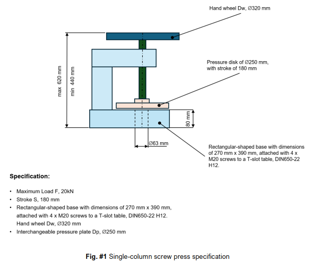
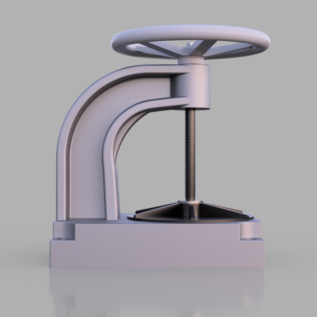
Single Power Screw Press Machine - Component and Connection Calculations

This project involves the design and optimization of a Single Power Screw Press Machine. The goal is to determine the calculations for each of its components and their interconnections for optimized performance.

Required Project Output

The project involves designing a Single Power Screw Press Machine, which includes selecting suitable materials, performing analytical and numerical validation, creating 3D CAD models, generating working drawings, and providing an assembly drawing. Finally, a calculation report will document the design methodology, results, and analysis to ensure optimal performance and safety.

1. A completed project must have:

Screw Press Design
Screw Press DesignScrew Press Design Details
Assembly ViewFinal Design

CALCULATIONS

2. Methods

The analysis followed systematic mechanical engineering design practices. Calculations were carried out using fundamental equations for:

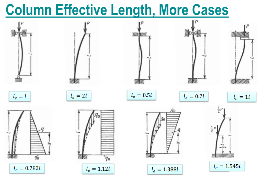
2.1 Compressive Buckling and Safety Factor Evaluation Using Johnson's Formula:

Define known inputs:

ParameterValue

PP

20kN20 kN

LL

180mm180 mm

EE

2.0105MPa2.0·10^5 MPa

nsn_s

33

SyS_y

550MPa550 MPa

Calculation Image

Determine Effective Length:

le(l)=0.7lle(l) = 0.7 · l

Calculate Minimum Required Core Diameter d:

d(P,le(l),E,ns)=32Ple2nsπ2Ed(P, le(l), E, ns) = \sqrt{\frac{32 \cdot P \cdot le^{2} \cdot ns}{\pi^{2} \cdot E}}

d(P,le(l),E,ns)=8.373mmd(P, le(l), E, ns) = 8.373 mm

Calculation Image

Select Thread Based on Required Diameter:

S22x3 with minor d = 16.794 mm is chosen

Calculation Image

Section Properties & Slenderness:

A(d)=πd24A(d) = \frac{\pi d^2}{4}

rg(A,I)=IArg(A,I) = \sqrt{\frac{I}{A}}

I(d)=πd432I(d) = \frac{\pi d^4}{32}

A(d)=221.512mm2A(d) = 221.512 \, \text{mm}^2

rg(A(d),I(d))=5.938mmrg(A(d), I(d)) = 5.938 \, \text{mm}

I(d)=(7.809×10³)mm4I(d) = (7.809 \times 10^3) \, \text{mm}^4

Ccr(rg,E,Sy)=2π2ESyC_{cr}(rg, E, Sy) = \sqrt{\frac{2 \cdot \pi^2 \cdot E}{Sy}}

C(e,rg)=ergC(\ell_e, rg) = \frac{\ell_e}{rg}

Ccr(rg,E,Sy)=84.722C_{cr}(rg, E, Sy) = 84.722

C(e,rg(A(d),I(d)))=21.221C(\ell_e, rg(A(d), I(d))) = 21.221

Buckling Check & Safety Factor:

σJ(Sy,e,E,rg)=SySy24π2E(e(l)rg(A(d),I(d)))2\sigma_J(S_y, \ell_e, E, r_g) = S_y - \frac{S_y^2}{4 \pi^2 E} \cdot \left(\frac{\ell_e(l)}{r_g(A(d), I(d))}\right)^2

σJ(Sy,e,E,rg)=532.747MPa\sigma_J(S_y, \ell_e, E, r_g) = 532.747 \, \text{MPa}

σ(P,A):=PA\sigma(P, A) := \frac{P}{A}

σ(P,A(d))=90.288MPa\sigma(P, A(d)) = 90.288 \, \text{MPa}

n:=σJ(Sy,e,E,rg)σ(P,A(d))n := \frac{\sigma_J(S_y, \ell_e, E, r_g)}{\sigma(P, A(d))}

n=5.901n = 5.901

2.2. Contact stress between the screw and the washer:

Wash material: High leaded Tin Bronze, UNS C93200, Copper casting alloy, Bearing Bronze SAE 660

Sub=240MPaS_{ub} = 240 \, \text{MPa}

Syb=120MPaS_{yb} = 120 \, \text{MPa}

Eb=100GPaE_b = 100 \, \text{GPa}

νb=0.35\nu_b = 0.35

Scb=320MPaS_{cb} = 320 \, \text{MPa}

HBb=65HB_b = 65

Screw

Washer (Bronze)

The diameter of screw head, washer groove:

da=60mmd_a = 60 \, \text{mm}

db=62mmd_b = 62 \, \text{mm}

E Modulus for both:

Ea=2105MPaE_a = 2 \cdot 10^5 \, \text{MPa}

Eb=1105MPaE_b = 1 \cdot 10^5 \, \text{MPa}

The poisson ratio:

νa=0.3\nu_a = 0.3

νb=0.35\nu_b = 0.35

Radius of the groove:

Ra=30mmR_a = 30 \, \text{mm}

Rb=31mmR_b = 31 \, \text{mm}

Calculation Image

Sign Convention:

R(rx,ry)  :=  (1rax+1rbx)1R(r_x, r_y) \;:=\; \left(\frac{1}{r_{ax}} + \frac{1}{r_{bx}}\right)^{-1}

1rax+1rbx1ray+1rby=1\frac{1}{r_{ax}} + \frac{1}{r_{bx}} \ge \frac{1}{r_{ay}} + \frac{1}{r_{by}} = 1

Rx:=R(rax,rbx)=930mmR_x := R(r_{ax}, r_{bx}) = 930 \, \text{mm}

Ry:=R(ray,rby)=930mmR_y := R(r_{ay}, r_{by}) = 930 \, \text{mm}

The effective radius:

Reff:=(1Rx+1Ry)1=465mmR_{\text{eff}} := \left(\frac{1}{R_x} + \frac{1}{R_y}\right)^{-1} = 465 \, \text{mm}

The radius ratio:

α:=RyRx=1\alpha := \frac{R_y}{R_x} = 1

Define the ellipticity parameter as:

ke(x):=x2πk_e(x) := x^{\frac{2}{\pi}}

ke(αr)=1k_e(\alpha_r) = 1

Φ(x):={π2+(π21)ln(x),1x100π2(π21)ln(x),0.01x<10,else\Phi(x) := \begin{cases}\frac{\pi}{2} + \left(\frac{\pi}{2} - 1\right)\ln(x), & 1 \le x \le 100 \\\frac{\pi}{2} - \left(\frac{\pi}{2} - 1\right)\ln(x), & 0.01 \le x < 1 \\0, & \text{else}\end{cases}

E(x):={1+(π22x),1x1001+(π21)x,0.01x<10,elseE(x) := \begin{cases}1 + \left(\frac{\pi - 2}{2x}\right), & 1 \le x \le 100 \\1 + \left(\frac{\pi}{2} - 1\right)x, & 0.01 \le x < 1 \\0, & \text{else}\end{cases}

The contact diameters are:

W:=20kNW := 20 \,\text{kN}

Dx(x,Reff,W,E):=2(6Φ(x)WReffπke(x)E)13D_x(x, R_{\mathrm{eff}}, W, E) := 2\left(\frac{6\cdot \Phi(x)\cdot W\cdot R_{\mathrm{eff}}}{\pi\cdot k_e(x)\cdot E}\right)^{\frac{1}{3}}

Dx:=Dx(αr,Reff,W,E)=11.414mmD_x := D_x(\alpha_r, R_{\mathrm{eff}}, W, E) = 11.414 \,\text{mm}

Dy(x,Reff,W,E):=2(6ke(x)2Φ(x)WReffπE)13D_y(x, R_{\mathrm{eff}}, W, E) := 2\left(\frac{6\cdot k_e(x)^2\cdot \Phi(x)\cdot W\cdot R_{\mathrm{eff}}}{\pi\cdot E}\right)^{\frac{1}{3}}

Dy:=Dy(αr,Reff,W,E)=11.414mmD_y := D_y(\alpha_r, R_{\mathrm{eff}}, W, E) = 11.414 \,\text{mm}

Hertz pressure distribution

The contact diameters:

dc:=Dx+Dy2=11.414mmd_c := \frac{D_x + D_y}{2} = 11.414 \,\text{mm}

Pressure distribution:

The maximum pressure

Pmax:=6WπDxDy=293.186MPaP_{max} := \frac{6W}{\pi \cdot D_x \cdot D_y} = 293.186 \,\text{MPa}

ph(x,y,Dx,Dy,Pmax):=Pmax(1(2xDx)2(2yDy)2)12p_h(x,y,D_x,D_y,P_{max}) := P_{max}\left(1 - \left(2\frac{x}{D_x}\right)^2 - \left(2\frac{y}{D_y}\right)^2\right)^{\frac{1}{2}}

ph(0.05Dx,0.09Dy,Dx,Dy,Pmax)=286.903MPap_h(0.05D_x,\,0.09D_y,\,D_x,\,D_y,\,P_{max}) = 286.903 \,\text{MPa}

The maximum deflection in the contact is:

δmax(x,Reff,W,E):=E(x)(92Φ(x)Reff(Wπke(x)E)2)13\delta_{max}(x, R_{\mathrm{eff}}, W, E) := E(x)\left(\frac{9}{2\Phi(x)\,R_{\mathrm{eff}}}\cdot\left(\frac{W}{\pi\,k_e(x)\,E}\right)^2\right)^{\frac{1}{3}}

δmax:=δmax(αr,Reff,W,E)=35μm\delta_{max} := \delta_{max}(\alpha_r, R_{\mathrm{eff}}, W, E') = 35 \,\mu\text{m}

The average compression stress:

A(dc):=πdc24A(d_c) := \pi \cdot \frac{d_c^2}{4}

σcomp:=WA(dc)=195.458MPa\sigma_{comp} := \frac{W}{A(d_c)} = 195.458 \,\text{MPa}

σcomp<Scb=1\sigma_{comp} < S_{cb} = 1

The safety factor for bearing load:

nc:=Scbσcomp=1.637n_c := \frac{S_{cb}}{\sigma_{comp}} = 1.637

2.3. Required assembly torque:

Selected thread S22×3:

Thread Data:

Pp=3mmP_p = 3 \,\text{mm}

dp=19.954mmd_p = 19.954 \,\text{mm}

Thread table

The friction coefficient in the thread:

μ:=0.12\mu := 0.12

The friction coefficient between screw and the bronze washer:

μc:=0.12\mu_c := 0.12

T(dp,ρ,α,P,rc,μc):=0.5dptan(ρ+α)P+rcμcPT(d_p,\rho,\alpha,P,r_c,\mu_c) := 0.5\,d_p\,\tan(\rho+\alpha)\,P + r_c\,\mu_c\,P

α:=arctan(Ppdpπ)=2.74\alpha := \arctan\left(\frac{P_p}{d_p \pi}\right) = 2.74^\circ

ρ:=arctan(μ)=6.843\rho := \arctan(\mu) = 6.843^\circ

rc:=dp2r_c := \frac{d_p}{2}

Max Torque:

Tmax:=T(dp,ρ,α,W,rc,μc)=57.632NmT_{max} := T(d_p,\rho,\alpha,W,r_c,\mu_c) = 57.632 \,\mathrm{N\cdot m}

Thread Torque:

Tthread(dp,ρ,α,P):=0.5dptan(ρ+α)PT_{thread}(d_p,\rho,\alpha,P) := 0.5\,d_p\,\tan(\rho+\alpha)\,P

Tact=33.688NmT_{act} = 33.688 \,\mathrm{N\cdot m}

Mating Face Torque:

Tmating(rc,μc,P):=rcμcPT_{mating}(r_c,\mu_c,P) := r_c\,\mu_c\,P

Tma_act=23.945NmT_{ma\_act} = 23.945 \,\mathrm{N\cdot m}

2.4. Force on Handwheel:

Size of the handle wheel:

Dhw:=315mmD_{hw} := 315 \,\mathrm{mm}

Ph:=TmaxDhw=182.96NP_h := \frac{T_{max}}{D_{hw}} = 182.96 \,\mathrm{N}

Given that the average maximum sustainable force applied by a human is typically considered to be around 250 N, the required force falls well within acceptable human ergonomic limits.

2.5. Checking stress in Screw:

dmin:=16.794mmd_{min} := 16.794 \,\mathrm{mm}

Shear stress due to torque:

τ(T,d):=Tπdmin316\tau(T,d) := \frac{T}{\frac{\pi \, d_{min}^{3}}{16}}

τmax:=τ(Tmax,dmin)=61.969MPa\tau_{max} := \tau(T_{max}, d_{min}) = 61.969 \,\mathrm{MPa}

Compression stress due to the force:

P:=W=20kNP := W = 20 \,\mathrm{kN}

σc:=PA(dmin)=90.288MPa\sigma_c := \frac{P}{A(d_{min})} = 90.288 \,\mathrm{MPa}

Equivalent stress:

σequ:=σc2+3τmax2=140.258MPa\sigma_{equ} := \sqrt{\sigma_c^{2} + 3\,\tau_{max}^{2}} = 140.258 \,\mathrm{MPa}

2.6. Structural assessment of nut:

Wash material: High leaded Tin Bronze, UNS C93200, Copper casting alloy, Bearing Bronze SAE 660

Sub:=240MPaS_{ub} := 240 \,\mathrm{MPa}

nns:=1.3n_{ns} := 1.3

dmj:=22mmd_{mj} := 22 \,\mathrm{mm}

Sb:=9.5MPaS_b := 9.5 \,\mathrm{MPa}

τall:=0.4.Sub=96MPa\tau_{all} := 0.4.S_{ub} = 96 \,\mathrm{MPa}

nr:=10n_r := 10

Shear stress in thread:

τ=Pπdrnrpψτallnss=0.6Sunss\tau=\frac{P}{\pi \cdot d_r \cdot n_r \cdot p \cdot \psi} \leq \frac{\tau_{all}}{n_{ss}} = \frac{0.6\,S_u}{n_{ss}}

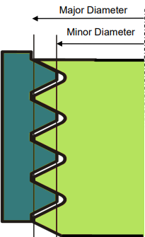
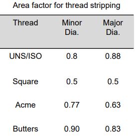
Minimum Nut Height to Prevent Thread Stripping:

The minimum thread convolution in the nut to avoid thread stripping:

nr,s(P,nr,d,p,ψ,τall):=Pnrπdpψτalln_{r,s}(P,n_r,d,p,\psi,\tau_{all}) := \frac{P \cdot n_r}{\pi \cdot d \cdot p \cdot \psi \cdot \tau_{all}}

Area factor for the major diameter (Buttress thread):

ψ:=0.83\psi := 0.83

nr,s(W,nr,dmj,Pp,ψ,τall)=12.106n_{r,s}(W,n_r,d_{mj},P_p,\psi,\tau_{all}) = 12.106

Minimum nut height due to shear stress:

hnut,s:=nr,s(W,nr,dmj,Pp,ψ,τall)Pp=36.317mmh_{nut,s} := n_{r,s}(W,n_r,d_{mj},P_p,\psi,\tau_{all}) \cdot P_p = 36.317 \,\mathrm{mm}

Permissible Bearing Pressure for Threaded Connections:

MaterialStationarySemi-MovableMovable
Gray Cast Iron EN-GJL-15012–15 MPa8–10 MPa4–5 MPa
EN-GJL-20016–20 MPa10–13 MPa6–6.5 MPa
EN-GJL-25020–25 MPa13–16 MPa6.5–8 MPa
Cast Steel 200–40025–30 MPa16–20 MPa8–10 MPa
Steel E295, E335, E36032–40 MPa22–27 MPa11–13.5 MPa
Brass24–28 MPa15–19 MPa7.5–9.5 MPa
Bronze32–40 MPa22–27 MPa11–14 MPa

Source: E. Mazanek, Examples of Calculations in Fundamentals of Machine Design, WNT, Warsaw, 2012 (translated).

The minimum height of the nut due to bearing stress:

nr,b(W,d,D1):=Wπ4(d2D12)Sbn_{r,b}(W,d,D_1) := \frac{W}{\frac{\pi}{4}\,(d^{2}-D_1^{2}) \cdot S_b}

hnut,b:=nr,b(W,dmj,dmin)Pp=39.817mmh_{nut,b} := n_{r,b}(W,d_{mj},d_{min}) \cdot P_p = 39.817 \,\mathrm{mm}

2.7. Efficiency of the thread:

P:=WP := W

η:=PPpTmax2π100=16.569%\eta := \frac{P \cdot P_p}{T_{max} \cdot 2\pi} \cdot 100 = 16.569\%

2.8. Key connection (Hand wheel – Power screw):

Parallel Key Connection Generator – Autodesk Inventor:

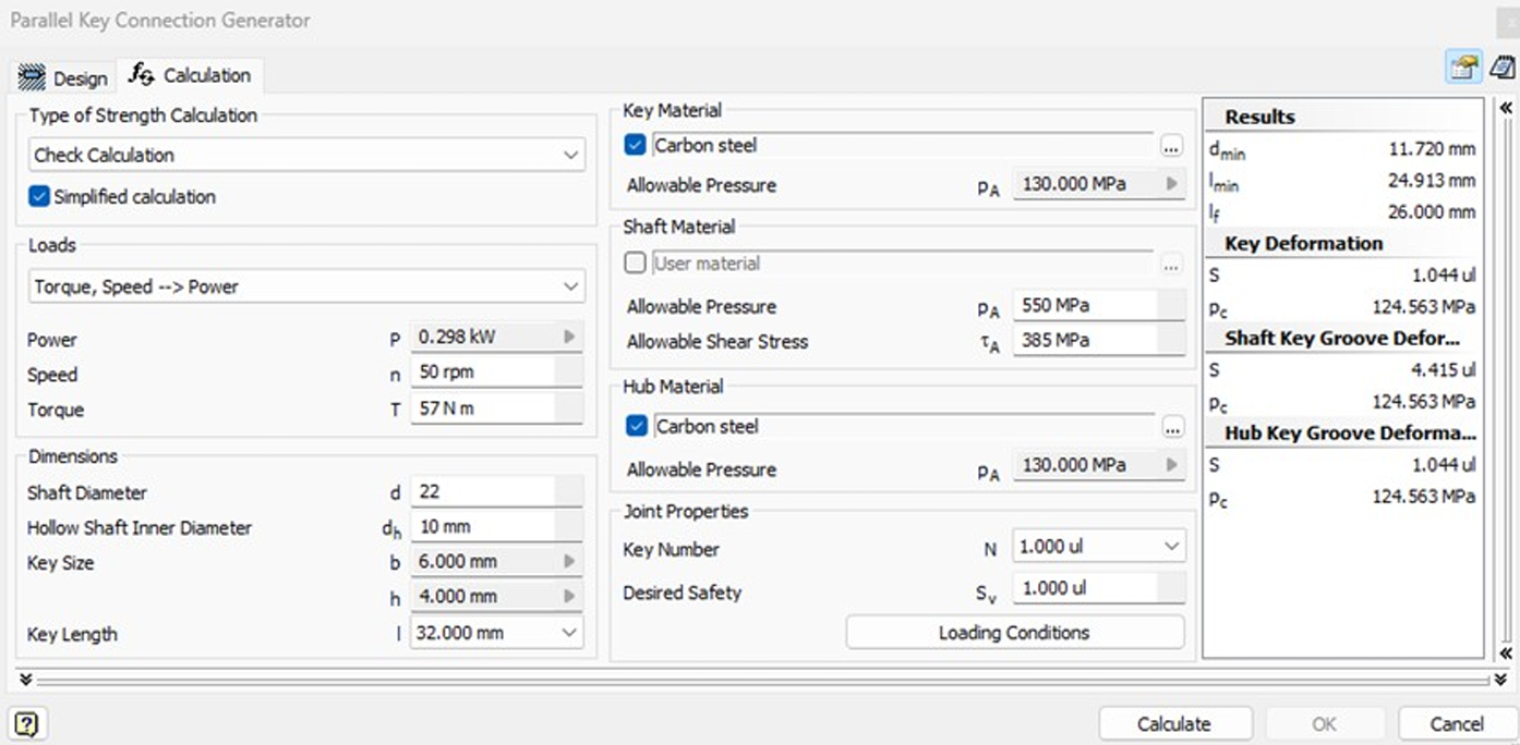
The key dimensions and safety verification were validated using Autodesk Inventor's Parallel Key Connection Generator module.

Torque: 57 N·m | Shaft diameter: 22 mm | Key size: 6×4 mm | Key length: 32 mm
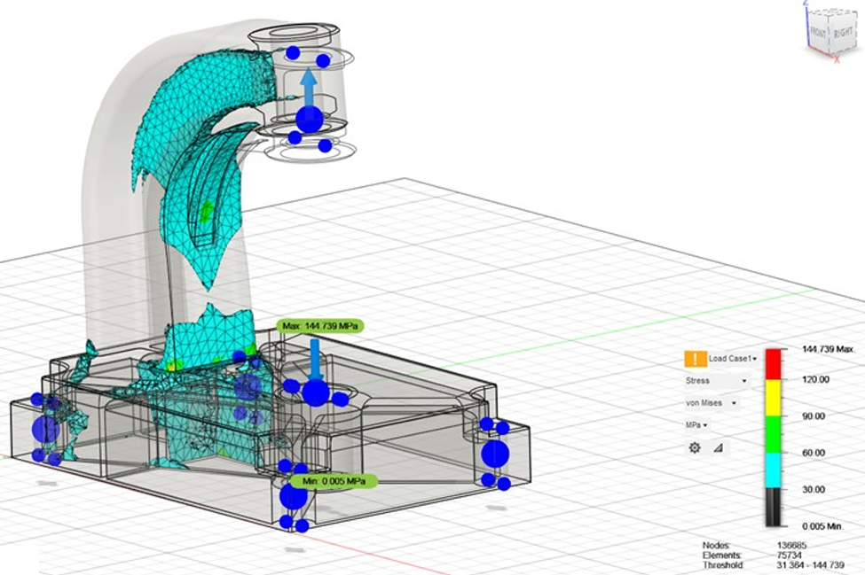
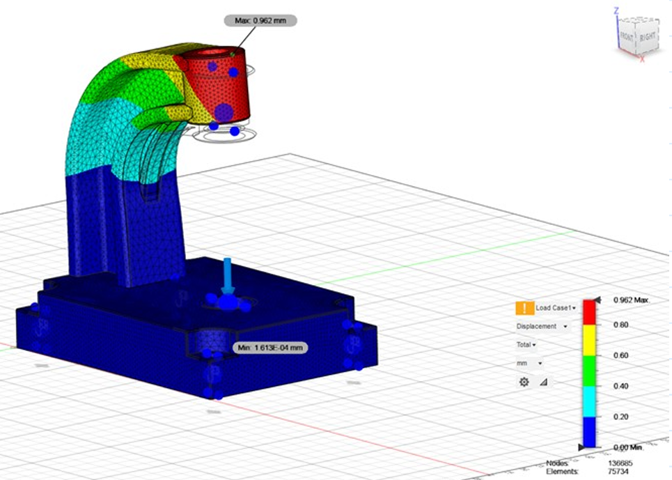
2.9. Base analysis:

Maximum Stress: 145 MPa

Maximum Displacement: 0.96 mm

Finite element analysis performed to evaluate stress distribution and structural displacement under maximum load conditions.

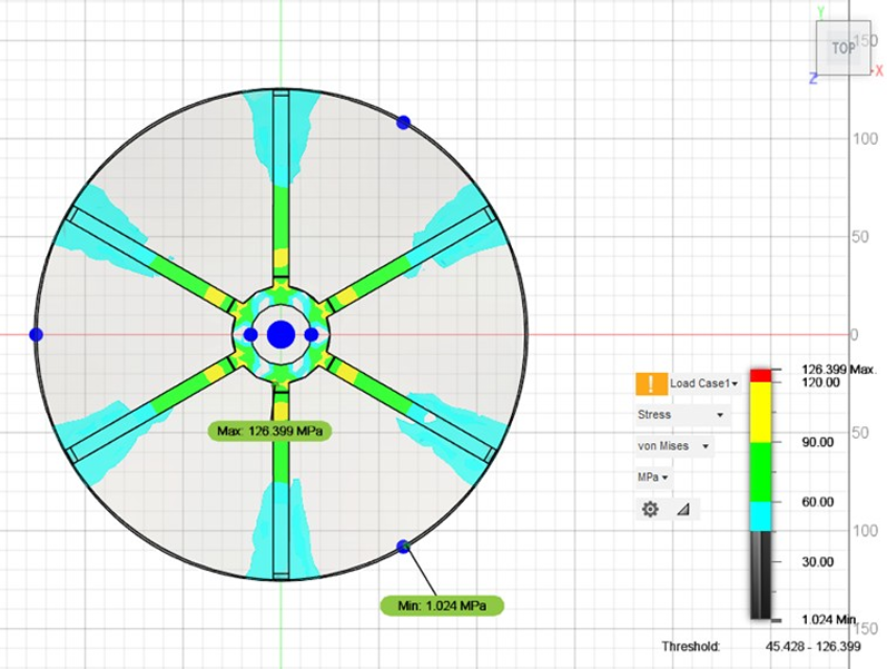
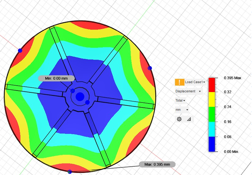
2.10. Pressure plate analysis:

Maximum Stress: 126 MPa

Maximum Displacement: 0.39 mm

Material properties and component dimensions were selected based on standard references such as Fundamentals of Machine Elements and Engineering Drawing and Design. Conservative design assumptions were applied.

RESULTS

3. Discussion

The results of the mechanical design and structural analyses are presented and discussed in the following sections. Detailed evaluations include screw selection and buckling verification, stress assessment of critical components, nut structural validation, torque and efficiency calculations, and contact stress evaluation at the screw–washer interface.

The subsequent sections include:

• 3.1. Screw Selection and Buckling Check

• 3.2. Stress Analysis

• 3.3. Nut Assessment

• 3.4. Torque Requirements and Efficiency

• 3.5. Contact Stress (Screw–Washer Interface)

3.1. Screw Selection and Buckling Check:

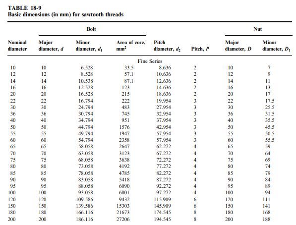
A thread type S22×3 with a minor diameter of 16.794 mm was selected. The calculated critical buckling stress was 532.747 MPa, and the applied stress was 90.288 MPa, resulting in a safety factor of 5.90

3.2. Stress Analysis:

Power screw:

Shear Stress: 61.969 MPa

Compression Stress: 90.288 MPa

Equivalent Stress: 140.258 MPa

All values were below material yield strength limits.

Base frame:

Maximum stress: 145 MPa

Maximum displacement: 0.96 mm

Pressure plate:

Maximum stress: 126 MPa

Maximum displacement: 0.39 mm

3.3. Nut Assessment:

Nut material: High-leaded Tin Bronze (SAE 660)

Shear strength $\tau_{all}$ = 96 MPa

Minimum height due to shear: 36.3 mm

Minimum height due to bearing stress: 39.8 mm

A final height of 40 mm was selected to satisfy both constraints

3.4. Torque Requirements and Efficiency:

Maximum required torque: 57.63 Nm

Thread efficiency: 16.57%

Handwheel force required: 182.96 N for a 315 mm diameter wheel

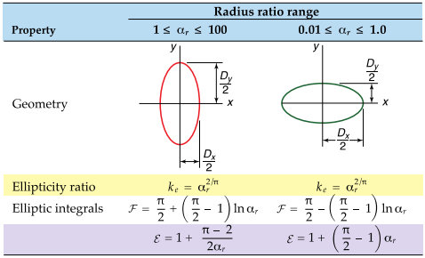
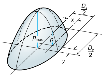
3.5. Contact Stress (Screw–Washer Interface):

Max contact pressure: 293.19 MPa

Average compression stress: 195.46 MPa

Safety factor: 1.64, which is within acceptable limits for bronze alloy interfaces

Conclusion

The structural and mechanical evaluations confirm the design’s safety and functionality under the given loading conditions. The screw-nut assembly, key connection, and base all meet design criteria with appropriate safety factors. Torque and efficiency values are acceptable for manual operation using a 315 mm handwheel.

No further reinforcement is needed, and all calculations align with classroom methodologies and literature standards.

References

1. Madsen, David A. Engineering Drawing and Design. Delmar Cengage Learning.

2. Schmid, Steven R. Fundamentals of Machine Elements. CRC Press.

3. Lecture slides and notes, Professor Slavomir Kedziora, MSPC-18, University of Luxembourg, 2025.

4. https://www.matweb.com/

Novin

An independent full-stack web developer from Ireland.

PAGES

HomeProjectsAboutNow

Version 1.0.0 – Date: Thursday 19 February at 18:44

RSSPrivacyMore Info

Built with Reflex